SHW Rotor System
Rotor system can be used for the reception area of bulk materials delivered externally in your plant. Bulk material can be brought in the further storage or transport process.
The equipment can also be used for the discharge of bulk materials from different types of silos.
An optimum unit for difficult to handle bulk materials stored in circular silos. Self-adjustment of the drag arm position and the driving torque control to the moving behaviour of the bulk material.
Component
Reception Component
Discharge Component
Applications
- Bulk material reception
- Bulk material intermediate storage
- Bulk material division within the process
- Combination with SHW-relief systems to prevent stable bridge buildup.
- The rotor discharge system is designed for cylindrical silos with flat bottom for diameters up to max. 7,500 mm.
- The rotor discharge system can be used for nearly all known difficult to handle bulk materials such as wood, paper, cement, gypsum, sludge and waste.
- Sewage Sludge:
- Slow flowing, compacts, abrasive
- Paper Waste:
- Fibrous, compacts / blocks
- Paper Sludge:
- Fibrous, compacts / blocks
- Coal Sludge:
- Slow flowing
- Dry Flakes:
- Compacts
- Sander Dusts:
- Compacts
- Wet Flakes:
- Compacts
- Shredded Waste Wood:
- Blocks, abrasive
- Wood Chips:
- Blocks, abrasive
- Bark:
- Compacts / blocks, abrasive, corrosive
- Secondary Fuels:
- Compacts / blocks, abrasive
- REA gypsum:
- Compacts
Photo Gallery

Technical Data
- Drive:
- 5.5 - 37 kW
- Dimensions:
- 2,000 - 7,000 mm diameter
- Weight:
- Up to 10 t
- Controls:
- Function, optional storage control
- Wear:
- As an option, specially tailored to the application and the bulk material, for example different stainless steels, Hardox, wear protection welding, Infinite Shield (ceramic)
- Execution:
- CE declaration of conformity
ATEX: standard no ex-qualification
Alternatives:
Inside: Zone 22 /
Outside: No Zone (EX II 3/-D)
Inside and Outside: Zone 22 (Ex II 3/3 D)
The silo diameter can vary from 2.5 m to approx. 7.5 m.
The drag arm sizes and constructions vary according to the silo diameter and the bulk material.
The patented relief elements are strategically placed inside the silo to reduce the pressure on the silo bottom and therefore supporting the operation of the discharge system. They prevent stable bridging inside the silo.
Technical Drawing

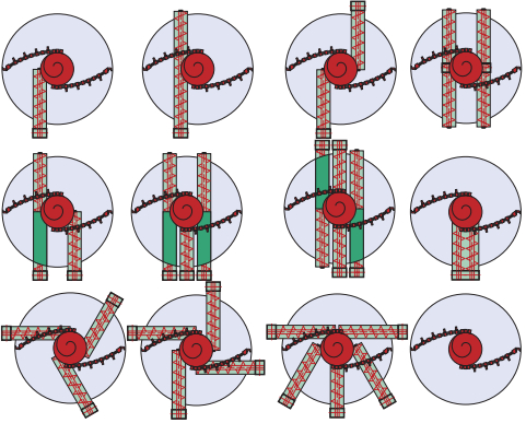
- Various possibilities for discharge screw positioning:

- Alternative digging tools:

Design Characteristics
- Robust construction
- Circular construction form
- Flexible or fixed drag arms
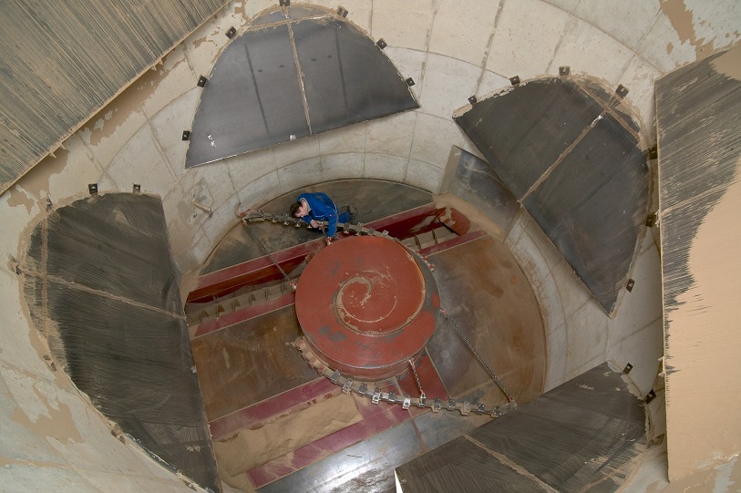
The rotor system is a patented silo technology and consists of the material relief system which reduces material compaction and the rotor discharge system with one or more discharge screws.
The rotor discharge system is installed in the centre of the flat silo bottom. The rotor drum consists of a welded steel construction on which drag arms are fixed which grab into the material.
The rotor drive consists of a planetary gear developed specifically by SHW with a specially designed spur gear unit. It is electric motor driven and controlled by a frequency converter.
Using multiple discharge screws in one silo it is possible to feed a metered quantity into different devises all at the same time. The material outlet can be arranged in many configurations to suit the system requirements.
Discharge Capacity
5 - 300 m3/h per discharge screw
Advantages
- Easy to maintain
- Continuous discharge
- Simultaneous feeding of up to six discharge screws

